
Copyright ©2019 Thomas Schwengler. A significantly updated and completed 2019 Edition is available.
CDMA systems spread a slow information bit rate with a fast chip sequence, transmit it over the air and retrieve the original information. How to actually spread and retrieve the information is standardized in details in IS-95. Three main tools are used:
The following sections go into further details on where these tools are used in various aspects of the IS-95 air interface: on forward links, reverse links, in access mode, and in traffic mode.
Walsh codes are orthogonal codes used extensively in cdmaOne and cdma2000.
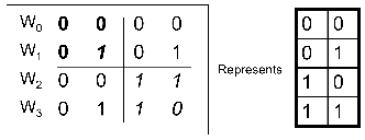
Generation by Hadamard matrices Walsh codes are simply built from Hadamard matrices as represented in figure 7.1. Hadamard matrices are built recursively, starting from H1 = [0] and ∀n > 1
![[ ]
H2n = Hn Hn-
Hn Hn](classweb182x.png) | (7.1) |
where Hn is the complimentary of Hn (switching zeros and ones).
For the following, we need to operate a slight transformation on the bits of information: instead of zeros and ones, we use instead signed bits and represent bit zero with +1 and bit one with –1. There is a convenient isomorphism between ({0,1}, mod 2 addition) and ({+1,-1}, multiplication). With this transformation, each bit of information is represented by a +1 or –1. This can simply be thought of as a simple binary phase shift: a +1 (bit 0) can be transmitted over the air by a sine wave at a given frequency, while a –1 (bit 1) can be transmitted by the opposite sine wave. In addition, gain can be added to the transmission by changing the amplitude of the sine wave.
With that convention in mind, we can model the use of Walsh codes in orthogonal sequences as used in the forward link of cdmaOne.
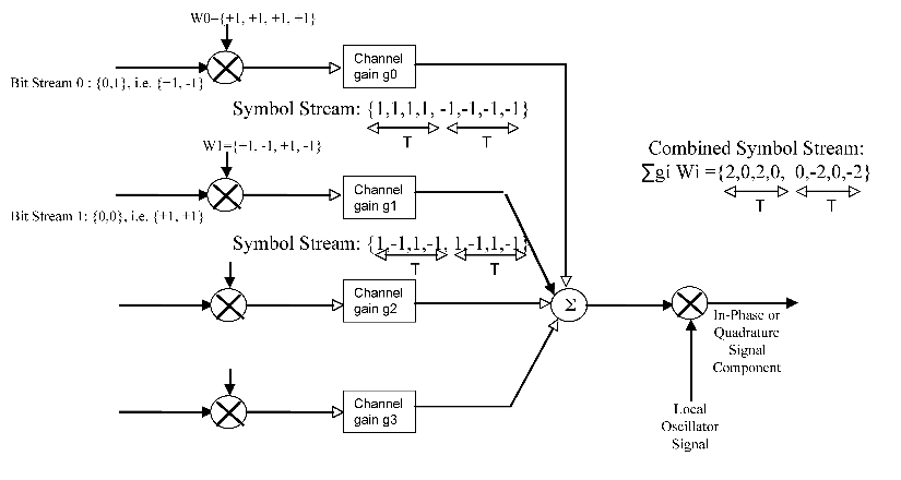
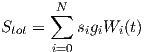
Forward Link Walsh codes are orthogonal codes, IS-95 uses them to multiplex several mobile communications (and control channels) on the forward link. In the forward link, each mobile uses a specific Walsh code sequence; all sequences are multiplexed together in a total combined sequence:
 | (7.2) |
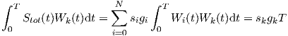
(where si represents the information symbol (+1 or -1), gi is the individual channel gain.) That sequence is manipulated further and sent over the air; on the receiver side, that sequence is decoded by simply integrating for each channel: for channel k, the information bit is retrieved from the sign of the integral:
 | (7.3) |
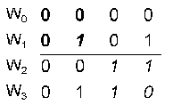
Reverse Link In the reverse link of IS-95, Walsh codes are not used in that manner but simply encode bits in a 64-ary encoding scheme: that s each 6-bit sequence is mapped to a 26 = 64 bit Walsh code. Figure 7.2 illustrate the example with 2 bits encoded by 22 = 4 bit Walsh codes.
In further evolutions like IS-2000 and IS-856, the reverse link multiplexes several channels similarly to the forward link, and Orthogonal properties of the Walsh codes provide the multiplexing scheme:
 | (7.4) |
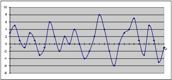
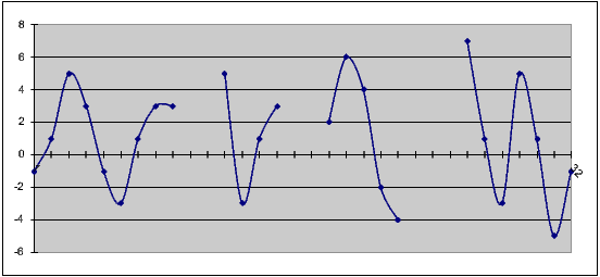
Encoding Example Figure 7.3 illustrates this CDMA spread spectrum. In the example, we encode two separate user bit streams: user 0 transmits the logical bitstream u0 = [0,1], which is physically represented by u0 = [+1,-1]. Each bit is encoded (“spread”) by Walsh code 0: W0 = [+1,+1,+1,+1], thus giving the represented symbol stream for user 0. Assume next that this symbol stream is amplified by some gain (here g0 = 1). Note that the gain may vary from one user to the next, and from one user bit to the next.
A similar stream is produce for user 1’s logical bitstream u1 = [0,0]. And more user bit streams could be added, but this example only shows two separate user streams u0 and u1, here transmitted wth equal gain g0 = g1 = 1.
Decoding Example Now examining figure 7.3, the initial user sequences can be retrieved by simply applying formula 7.3 for every Walsh code, and bit by bit. The reader is invited to try to multiply bit by bit the sequence of figure 7.3, and integrate (which is here straightforward since piecewise constant functions are involved) to retrieve the user bit value (+1 or -1). A further exercise is given at the end of the section, where the total symbol sequence is given (see figure 7.15) and the reader is invited to retreive each user sequence (ui) and gain (gi).
Short codes are bit sequences with very specific autocorrelation functions. IS-95 uses a 215 - 1 = 32767 chip short code. For a first example let us use here a 22 - 1 = 3 bit long short code: 100.
Permutated, that short code has the following property: if +1 is counted for every bit of the permutated sequence that is identical to the bit of the original sequence, and -1 is counted when that bit is different, every permutated sequence totals -1, whereas the original sequence obviously totals its length (here 3).
| 100 |
|
| 010 | +1 agreement -2 disagreements = -1 |
| 001 | +1 agreement -2 disagreements = -1 |
| 100 | +3 agreement -0 disagreements = 3 |
If we note < S,S(n) > the above computation, we have for a short code sequence:
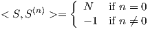 | (7.5) |
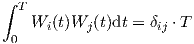
This is a remarkable property of autocorrelation between bit sequences that is used in CDMA. As another example, verify the following two short code sequences (of length 23 - 1 = 7) verify the same property as the table above: s1 = 0011101 and s2 = 1110010. These two sequences are used for Gold codes in other CDMA standards. And another short code (of length 25 - 1 = 31) is s3 = 0000101011101100011111001101001.
IS-95 uses a much longer such sequence (215 - 1 = 32768 chips) which provides many possible sequences orthogonal to one another, used to differentiate between sectors on the forward link.
Long code is a sequence of bits used for its pseudo-orthogonal properties; that much longer sequence does not have the perfect autocorrelation properties as the short code, but a similar one such that:
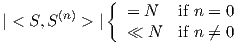 | (7.6) |
This pseudo orthogonal property is used in IS-95 reverse link in a 1.2288Mcps chip sequence to differentiate between mobiles. On the forward link the long code is decimated down to a 19.2kbps bit stream for a unique user mask.
cdmaOne, or IS-95 commonly refers to the first implementations of CDMA techniques as invented by Qualcomm Inc. We first review the basic functions of IS-95 CDMA channels, and we will build on these to understand further IS-2000 improvements in the next section.
During a call, both traffic and certain control data are embedded in the forward-link channels. Three forward-link control channels, the pilot channel, the synchronization channel, and the paging channel, are discussed in this section.
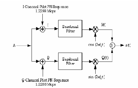
Pilot Channel The primary purposes of the forward-link pilot channel are to allow mobile units to detect the presence of a sector and to provide some form of timing reference for those mobiles so that coherent demodulation can be accomplished on the other forward-link channels. Detection of pilot channel power levels is also used to control handoff.
Synchronization Channel The synchronization channel transmitted by each sector is used along with the pilot channel to provide important system information to the mobile unit, such as revision (IS-95A, B, or IS-2000), system ID, Network ID, system time, long code state, etc.
Paging Channel One or more paging channels can be utilized within each sector of a CDMA system to inform mobile units of incoming calls, to convey channel assignments during call setup, and to transmit other overhead system information to the mobile units. The forward-link paging channel is used to set up a call, or to exchange short messages (SMS) in idle mode. But once a call is established, the sector transmits information specific to a particular mobile unit within the forward-link traffic channel.
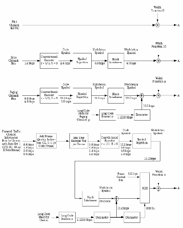
The forward-link traffic channel carries user data such as voice communication. The forward-link voice traffic is parsed into 20-ms frames. On a frame-by-frame basis, bit rates associated with the particular Rate Set being employed by the connection are allowed. Frame Quality Indicator (FQI) bits are added as appropriate to these bit streams so that the mobile unit can apply a Cyclical Redundancy Check (CRC) to evaluate whether there are errors in the frame or not after reception. Finally, an 8-bit encoder tail is appended to the frame.
Different convolutional encoding schemes and symbol repetition are then applied for different vocoding rates to achieve a fixed bit rate of 19.2 kbps as set by the IS-95 standard. For less-than-full-rate frames, symbol repetition is applied as appropriate such that the equivalent overall data rate is still 19.2 kbps after symbol repetition.
Finally, after convolutional encoding, symbol repetition, and block interleaving, the bit stream is effectively multiplied by the decimated “Long Code”. Note that there is a single long PN code utilized by the system, based on system time (and hence aligned with Universal Coordinated Time). This PN code runs at a rate of 1.2288 Mcps, and still only repeats every 41 days due to the length of the code and the design of the shift register used to generate this long code. This long code is decimated, or sampled every 64th bit, and the resulting 19.2-kbps stream is the decimated long code which multiplies the traffic channel bit stream of interest.
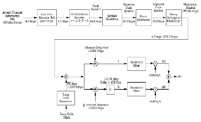
The reverse-link access channel is used to access the system during call setup; it is used to request service or to answer a page for an incoming call. The mobile unit makes an Access Attempt, in which it repeatedly attempts to access the system until either the network responds or the maximum number of attempts have been made.
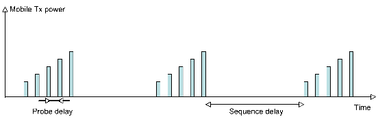
Within each Access Attempt, the mobile unit transmits a series of Access Probe Sequences, each separated by a waiting period to allow the system time to respond. If a response is obtained, then no more Access Probe Sequences are sent, if a maximum settable number of Access Probe Sequences are sent without a response from the network, then the mobile unit will discontinue trying to contact the network. Each Access Probe Sequence within an Access Attempt consists of a series of Access Probes, each separated by a waiting period to allow the system time to respond to each probe, and increasingly powerful.
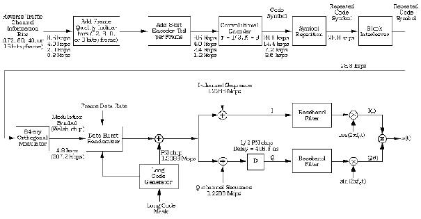
The reverse-link traffic channel processes user information such as voice in successive processing steps. The first step is to add Frame Quality Indicator (FQI) bits, which allow the base station to determine whether errors occurred during transmission via a Cyclical Redundancy Check (CRC). After the addition of the FQI bits, encoder tail bits are added to each 20-ms frame. The result is a bit stream at a rate determined by the Rate Set selected for the connection (as established at call setup through negotiation between the network and the mobile unit) and the sub-rate required to transmit the information for that individual 20-ms frame.
A convolutional encoder followed by symbol repetition is then employed to achieve a 28.8-ksps stream. The resulting bit stream is then sent through a 576-bit interleaver (576 bits per 20-ms frame) to mitigate burst errors during transmission.
On the reverse link, Walsh codes are used for modulation rather than to discriminate between separate traffic channels. For each six sequential bits in the coded and interleaved voice frame, a 64-bit Walsh code is transmitted, depending on the values of the 6 input bits (called 64-ary modulation).
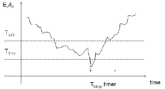
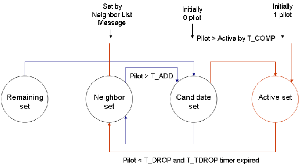
CDMA introduced soft handoff, in which a mobile may be in communication with several sectors or cells at the same time; it is a great technique to provide seamless fast transitions between cells. Soft handoff is typically a mobile assisted procedure: the mobile unit detects pilot strengths from various sectors and reports them (via Pilot Strength Measurement Message) to the base station. The decision is then made to add, drop or replace sectors according to set power thresholds and timers (Tadd, Tdrop, Ttdrop).
The handoff process is based on several sets, populated by different possible PN offset values that may be used by the mobile for soft handoff. Figure 7.10 summarizes these sets and the processes in place to promote a possible sector seen by the mobile from any set to the next as their power level exceeds given thresholds (and conversely to demote them as their power weakens).
Over time, the handoff process was improved (from IS-95A to IS-95B, to IS2000) with new features, including the following:
Copyright ©2018 Thomas Schwengler.
These features increase capacity and improve call setup statistics.
Power control is essential (although not mandatory) in a CDMA system to resolve the near-far problem. Forward-link and reverse-link power control are very different in nature and are discussed separately.
Forward-Link Power Control At the initiation of a call, the serving sector begins transmitting the forward-link traffic channel at a fixed default power level. After connection is established, a form of close-loop forward-link power control takes over, in which the mobile unit reports the quality of the received forward-link signal and the sector responds by adjusting the power allocated to that connection.
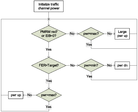
For Rate Set 1 calls (9.6kb/s), the mobile unit reports frame errors via a Power Measurement Report Message embedded in the reverse-link traffic channel. The reporting is usually periodic or can be threshold-based. Typically the sector will periodically reduce the transmit power allocated to a specific traffic channel, by small steps (typically between 0.2 dB and 0.5 dB), as long as it receives a Power Measurement Report Message (PMRM). When a PMRM is not received, it then increase its transmit power by a larger increment (1-2dB up to a maximum).
For Rate Set 2 Calls (14.4kb/s), forward-link power control is simpler: the mobile sends a forward-link Erasure Indicator Bit (EIB) in each reverse-link traffic-channel frame to indicate whether the most recent frame was in error or not based on the Cyclical Redundancy Check (CRC). In good conditions (no erasures reported), the base lowers power in the traffic channel by dn_adj (typically 0.2 dB to 0.5 dB). If an erasure is reported, the traffic channel needs more power, and the base powers up by up_adj (typically higher than dn_adj, such as 1 dB).
Reverse-Link Power Control In an IS-95 system, reverse-link power control is performed at an effective rate of 800 Hz. That is, every 1.25 ms, the mobile unit will either power up or power down in response to the various power control commands that it receives from the serving sectors.
Open-Loop Reverse-Link Power Control Open-loop power control is utilized to establish a connection between a base station and a mobile unit. This applies particularly to the reverse-link access channel and the reverse-link traffic channel before closed-loop power control takes over. Under open-loop power control, the mobile unit estimates the required reverse-link transmit power for the signal to be detected at the base station based on the received power in the forward-link pilot channel. This open-loop estimate for the transmit power is given by a formula similar to the following:
 | (7.7) |
where K is a so-called turn-around constant, PRx is the received pilot-channel power in dBm, and NOM_PWR and INIT_PWR are parameters that can be changed by the network operator to adjust the initial power that mobile units throughout the network use to initially access the system. K is typically -73 dB for cellular-band CDMA whereas K is typically -76 dB for PCS-band CDMA.
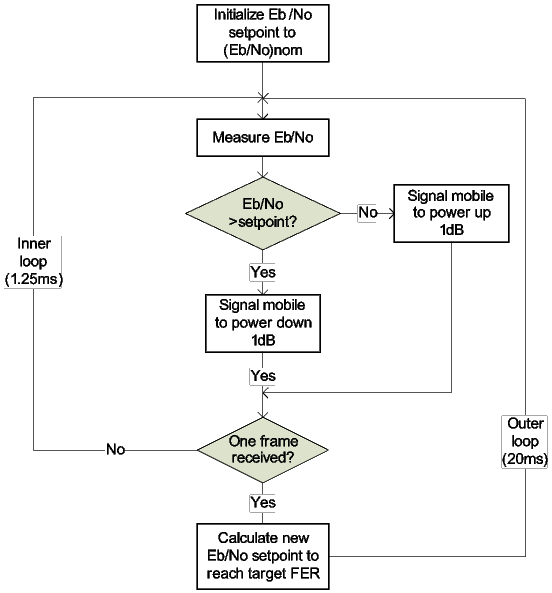
Closed-Loop Reverse-link Power Control (Outer Loop) Each individual call being supported by a base station has a target Eb∕N0 set point (ratio of energy per transmitted information bit to the power spectral density of the noise plus interference floor) associated with that call. When the connection is initiated, a default value (Eb∕N0) nomisassignedtothistargetE˙b/N˙0.Typicaldefaultvaluesareontheorderof7dBformobilesubscribers.
The reverse-link Frame Erasure Rate (FER) truly characterizes the absolute quality of the received signal, not the Eb∕N0 value. The network operator therefore specifies a desired voice quality by setting a target FER. Values of 1-2% are typical. The outer-loop reverse-link power control periodically adjusts the target Eb∕N0 set point to achieve the desired FER. If for some period of time the FER is nearly 0%, then this target Eb∕N0 value can be decreased slightly. If, on the other hand, the desired FER is being exceeded, then this target Eb∕N0 value will be increased slightly to improve the FER. The network operator can typically set absolute minimum and maximum bounds beyond which this Eb∕N0 set point cannot be adjusted by the outer-loop power-control algorithm.
Closed-Loop Reverse-Link Power Control (Inner Loop) The channel element within any base station supporting the call essentially continuously monitors the effective Eb∕N0 of the reverse-link signal that it has received from the mobile unit. Every 1.25 ms, it compares the actual measured Eb∕N0 value to the particular target Eb∕N0 set point that has been determined to be required to maintain call quality via the outer-loop reverse-link power control. If the measured Eb∕N0 value is lower than the target Eb∕N0, then a power-up command is issued to the mobile unit for this 1.25-ms interval. If the measured Eb∕N0 value is higher than the target Eb∕N0, then a power-down command is issued to the mobile unit for this 1.25-ms interval. Note that either a power-up or power-down command is issued. There is no corresponding command for no power adjustment of the mobile unit.
We now review the basic functions of IS-2000 CDMA channels, focusing on differences and improvements compared to IS-95. IS-2000 CDMA systems are similar to IS-95 systems, and still use the fundamental three tools of IS-95, but in different ways, and with additional improvements:
IS-2000 specifies a spread spectrum radio interface that uses Code Division Multiple Access (CDMA) technology to meet the requirements for 3G wireless communication systems. IS-2000 is a family of standards that deal with all aspects of cdma2000 systems: physical layer, Medium Access Control (MAC), Signaling Link Access Control (LAC), and Upper Layer (Layer 3); in addition, a standard specifies analog operation, to support dual-mode mobile stations and base stations. Throughout this text, use of the term cdma2000 or IS-2000 refers to this family of standards.
The IS-2000 forward link is composed of the following channel types:
The IS-2000 reverse link is fundamentally different from IS-95, it is composed of several orthogonal channels, multiplexed on different Walsh codes (thus resembling a little more the IS-95 forward link channel structure, including the presence of a reverse pilot channel). And the 64-ary modulation by Walsh codes is only used in radio configurations 1 and 2 for 2G backward compatibility, but is not used for the 3G radio configurations 3 and higher.
Power control systems and typical algorithms are reviewed for IS-2000, and compared to the IS-95 capabilities. Note that for radio configurations 1 & 2 (RC1 & RC2), no 3G improvement exist due to backward compatibility. In the remaining of the section, when we examine “3G power control”, it concerns RC3 to RC6. Specific power control considerations for packet data are also briefly presented.
Forward Link Power Control The 2G forward link power control is based on mobile station reporting frame quality: For rate set 1, the mobile reports frame error information in Power Measurement Report messages (PMRM) as long as the frame error rate (FER) is below a set threshold. In rate set 2, the mobile uses the Erasure Indicator Bit (EIB) to indicate a bad frame; the base may then keep track of FER, and accordingly adjust power levels. The 3G forward link power control is much improved (for radio configuration 3 to 6), and more closely related to the 2G reverse link power control: it operates at a 800Hz; it involves both the mobile station and the base station. For voice: the mobile reports commands on the reverse pilot channel for the base to power up or down, every 1.25ms, based on the comparison of estimated Eb∕Nt with a set point (inner-loop), that set point is updated every frame (20ms), based on the target FER (outer-loop). For data, the scheme is very similar, with the following nuances:
Reverse Link Power Control The 2G reverse link power control had an open-loop and a closed-loop (with an inner and outer-loop). The 3G reverse link open-loop power control resembles that of 2G (or RC1 & RC2), but requires a few new parameters due to the presence of the reverse pilot channel (R-PICH). The mean output power of the latter is computed from the last access channel power (P(R-ACH)) and a set offset (RLGAIN_ADJ) as follows:
 | (7.8) |
Subsequently the mean traffic channel (fundamental channel R-FCH) power is computed by a fixed offset:
 | (7.9) |
For voice, the 3G reverse link closed-loop power control is similar to 2G, since it operates at 800Hz inner-loop, 50Hz outer-loop, but is based on the reverse pilot channel, which simplifies the algorithm. Indeed the presence of the R-PICH, continuous, not gated, allows the base station (inner-loop) to simply measure the R-PICH Ec∕I0 (not the R-FCH Eb∕Nt), and to send power up/down commands accordingly. The outer-loop sets a frame-by-frame Ec∕I0 set point based on the target FER.
For data, the algorithm is similar, but with different set points; data and voice channels use different target FER, and different initial Eb∕Nt, set points. Also, (unlike the forward link) cdma2000 supports only one inner-loop on the reverse link. Consequently, when supplemental channels are used, the mobile applies the inner-loop power control commands to the R-FCH and R-SCH. Two outer-loops still exist, one for R-FCH, and one for R-SCH, since the two have different set points and target FER.
Although mostly presented as an evolution for GSM operators, UMTS and its underlying air interface standard wideband CDMA (WCDMA) are an evolution of cdmaOne, inasmuch as they resemble the latter much more than a TDMA standard such as GSM.
We introduce WCDMA with an emphasis on comparison with the cdmaOne and cdma2000 line of standards.
As seen above, WCDMA implements fast closed-loop power control much like cdma2000 (slightly faster). Additionally, WCDMA implementations may use some flavor of multi-user detection, which we briefly treat here. Multi-user detection algorithms may be optimal or sub optimal.
Multi-user detection may be used in the forward and reverse link. The two schemes are very different in concept. The forward link is synchronous and has very different power levels multiplexed for each mobile (due to their varying distance to the base station). The reverse link, on the other hand, is asynchronous and the received signals are all power-controlled to reach the receiver at comparable amplitude. Also the base station must decode all users, whereas the mobile is only interested in one traffic channel and a pilot (one proposal suggests to only cancel that pilot, which must be decoded by the handset anyway). Finally, the computing power available at the base station is much greater than the mobile’s.
The items listed above show the close proximity of the spirit of WCDMA with that of cdma2000. We’ve seen already that the few major differences could not be ironed out more out of legal and business reasons than out of technical incompatibility. The result of having two major standards so close in their fundamentals is a shame in some respect, but it might also be viewed as yet another degree of freedom for certain operators. Indeed operators reluctant to use the US controlled GPS system see an alternative in asynchronous WCDMA.
Copyright ©2018 Thomas Schwengler.
Practically the air interface is only the tip of the iceberg, the underlying network infrastructure is an important part of the standard evolution: cdma2000 manufacturers built their evolution around the same network standard as cdmaOne (IS-41), whereas WCDMA equipment used GSM-MAP. Standards considered hooks between network interfaces and air interfaces to ideally allow any network to work with either air interface. Practically however, the industry saw little interest to pursue that effort.
The above CDMA evolutions are part of the third generation of mobile standards (3GPP, 3GPP2); recall that their main requirements were two-fold: to increase voice capacity and to allow higher data rates (higher than the few multiples of 9.6 or 14.4 kbps that is). Subsequently however much higher peak rates in the megabit rage were needed, and standards appeared to address that need, standards like 1x-EV-DO (1-channel evolution - data optimized, 1-channel referring to the previously used cdmaOne 1.25MHz frequency channel) , and HSPA (High-speed packet access).
EVDO is a data standard for the cdmaOne-cdma2000 (3GPP2) line of product. It initially optimizes the forward link for high speed data, for targeted applications such as Web browsing, file transfer, VoIP, push-to-talk, video streaming, video conferencing.
EVDO is also a CDMA standard, also works in a 1.25MHz frequency channel (or multiple 1.25MHz channels), and is similar in some aspects: it uses Wash codes, short codes, and long codes. But is different in several ways: it now uses turbo codes, and a hybrid ARQ (for early termination of forward link packets), it uses adaptive modulation (QPSK to 16QAM). EVDO has several releases:
Forward Link One of the main fundamental difference of EVDO is in its forward link: orthogonal channels are no longer transmitted simultaneously for multiple users, instead, one user receives the entire set of channels in one given time slot. EVDO is thus a time divided multiplexed standard (TDM); see figure 7.14.
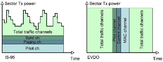
Similarly, a pilot channel and control channels exist in their own time slot, during which do actual user data is transmitted. This schemes needs no forward-link power control since at any time the entire sector power is dedicated to one given user; instead the modulation varies to adapt to the link condition. EVDO adapts modulation rate on the forward link from QPSK, to 8PSK, to 16QAM, depending on the wireless channel conditions.
Another novelty is the use of virtual soft-handoff in which a client device in handoff may transmit to several base stations, but on the forward link, only one sector (estimated the best at the time) transmits to the client. This soft handoff is very efficient in providing macro-diversity on the reverse link while optimizing throughput and limiting interferences on the forward link.
Reverse Link The EVDO reverse link is much more like cdma2000: it is a CDMA link; it is power controlled for pilot and MAC channels, with the now familiar closed and open loop; power of user data channel vary with data rate. Walsh codes (of length 4, 8, and 16) are used for orthogonal channels, including pilot (W016), DRC (W816), ACK (W48), Data (W24).
Copyright ©2019 Thomas Schwengler. A significantly updated and completed 2019 Edition is available.