

Copyright ©2019 Thomas Schwengler. A significantly updated and completed 2019 Edition is available.
Providing wireless service over wide areas requires different schemes to efficiently use spectrum in different locations while avoiding interference.
Covering a large geographic area with limited amount of spectrum leads to the reuse of the same frequency in multiple locations; this leads to co-channel interference considerations, meaning interference from different areas (or cells) that use the same frequency channel.
Co-channel interference considerations are usually approached by considering the following parameters:
The three quantities are linked by the straightforward relation:
 | (2.1) |
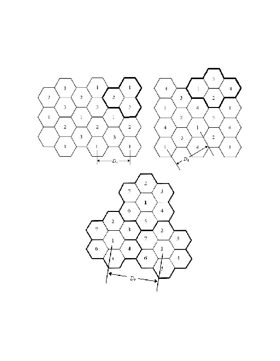
The reuse factor K is therefore an important parameter for capacity. The lowest reuse factor (K = 1) maximizes capacity; but this has to be balanced with interference considerations: indeed a higher reuse factor (K = 3, 4, 7, or higher) provides more distance between cells using the same frequency, which lowers interferences.
Spectrum reuse causes interference; quantifying them require us to consider how a signal propagates from one cell to another. We will study propagation models later in chapter 3, but we need a few simple notions here. Assume a propagation model using a power path loss exponent n, that is a model where power decays in 1∕Rn (R being the distance separating transmit station from receiver). This means that the ratio of received power to transmit power may be expressed as Pr∕Pt = A∕Rn, where A is some constant.
With this model, signal to interference ratios are estimated as
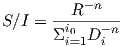 | (2.2) |
where i0 is the number of co-channel cells nearest to the cell (called first tier or tier one); that number increases with K. And Di is the distance to the tier-one cells reusing the same frequency (as shown in figure 2.1). In the case of hexagonal cell approximation the expression simplifies to [1]:
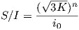 | (2.3) |
We’ll see more details on n further, its values vary typically between 2 and 4 with the types of terrain. We’ll also see that specific wireless technologies require a certain signal to noise and interference ratio (mostly based on data rates); so equation (2.3) leads to a minimal acceptable value for K.
A major requirement of cellular networks is to provide an efficient technique for multiple devices to access the wireless system. These techniques include:
These are the main multiple access techniques, but subtle extensions and combinations can be devised to obtain more efficient schemes, which we will examine in later chapters (including orthogonal frequency division multiplexing - OFDMA).
Wireless communications deal with at least two main concerns: coverage and capacity. We will look at coverage prediction in the next chapters, and start here with a few words on capacity.
One fundamental concept of information theory is one of channel capacity, or how much information can be transmitted in a communication channel. In the 1940’s Claude Shannon invented formal characterization of information theory and derived the well-known Shanon’s capacity theorem (Theorem 17 in [15], p.628). That theorem applies to wireless communications. A great presentation of this equation can be found in [8] p.82; it presents a concise derivation of the equation, and includes a good introduction to important information theory concepts such as information and entropy. 1
The Shannon capacity equation gives an upper bound for the capacity in a non-faded channel with added white Gaussian noise:
 | (2.4) |
where C= capacity (bits/s), W=bandwidth (Hz), S∕N= signal to noise (and interference) ratio.
That capacity equation assumes one transmitter and one receiver, though multiple antennas can be used in diversity scheme on the receiving side. The formula will be revisited for multi-antenna systems in §9.1.3. The equation singles out two fundamentally important aspects: bandwidth and SNR. Bandwidth reflects how much spectrum a wireless system uses, and explains why the spectrum considerations seen in §1.2 are so important: they have a direct impact on system capacity. SNR of course reflects the quality of the propagation channel, and will be dealt with in numerous ways: modulation, coding, error correction, and important design choices such as cell sizes and reuse patterns.
Practical capacity of many wireless systems are far from the Shannon’s limit (although recent standards are coming close to it); and practical capacity is heavily dependent on implementation and standard choices.
Digital standards deal in their own way with how to deploy and optimize capacity. Most systems are limited by channel width, time slots, and voice coding characteristics. CDMA systems are interference limited, and have tradeoffs between capacity, coverage, and other performance metrics (such as dropped call rates or voice quality).
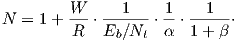 | (2.5) |
where
This simple equation (2.5) gives us a number of voice channels in a CDMA frequency channel 2.
We can already see some hints of CDMA optimization and investigate certain possible improvement for a 3G system. In particular: improving α can be achieved with dim and burst capabilities, β with interference mitigation and antenna downtilt considerations, R with vocoder rate, W with wider band CDMA, Eb∕Nt with better coding and interference mitigation techniques.
Some aspects however are omitted in this equation and are required to quantify other capacity improvements mainly those due to power control, and softer/soft handoff algorithms.
Of course other limitations come into play for wireless systems, such as base station (and mobile) sensitivity, which may be incorporated into similar formulas; and further considerations come into play such as: forward power limitations, channel element blocking, backhaul capacity, mobility, and handoff.
Modulation techniques are a necessary part of any wireless system, without them, no useful information can be transmitted. Coding techniques are almost as important, and combine two important aspects: first to transmit information efficiently, and second to deal with error correction (to avoid retransmissions).
A continuous wave signal (at a carrier frequency fc) in itself encodes and transmits no information. The bits of information are encoded in the variations of that signal (in phase, amplitude, or a combination thereof). These variations cause the occupied spectrum to increase, thus occupying a bandwidth around fc; and the optimal use of that bandwidth is an important part of a wireless system. Various modulation schemes and coding schemes are used to maximize the use of that spectrum for different applications (voice or high speed data), and in various conditions of noise, interference, and RF channel resources in general.
Classic modulation techniques are well covered in several texts [1][8], and we simply recall here a few important aspects of digital modulations (that will be important in link budgets). The main digital modulations used in modern wireless systems are outlined in table 2.1.
Modulation | Bits encoded by: | Examples |
Amplitude Shift Keying | Discrete amplitude levels | On/off keying |
Frequency Shift Keing | Multiple discrete frequencies |
|
Phase Shift Keying | Multiple discrete phases | BPSK, QPSK, 8-PSK |
Quadrature Ampl. Mod. | Both phase and amplitude | 16, 64, 256 QAM |
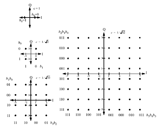
Modulation is a powerful and efficient tool used to encode information; a few simple definitions are commonly used:
Higher order modulations can encode multiple bits in a symbol, and require higher SNR to decode error-free. Figure 2.2 illustrates how multiple phases and amplitudes are used to combine multiple bits into one symbol transmission. The tradeoff between bits encoded per symbol is often referred to as a measure in bits per Hertz (b/Hz), its relation to SNR is bounded by Shannon’s theorem seen earlier (§2.2.1).
Efficient coding schemes are the powerful engines behind the growth of the wireless industry. They have allowed wireless systems to be both spectrally efficient and robust in terms of error corrections.
Block coding are the classical approach: blocks of data are used as input to produce usually larger output blocks containing added redundancy.
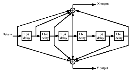
Second generation wireless systems like cdmaOne introduced the use of convolutional coding. The coding scheme provides an efficient redundant and error-correcting scheme. This is particularly useful for voice transmission where the need for retransmission causes delays and degrades voice quality.
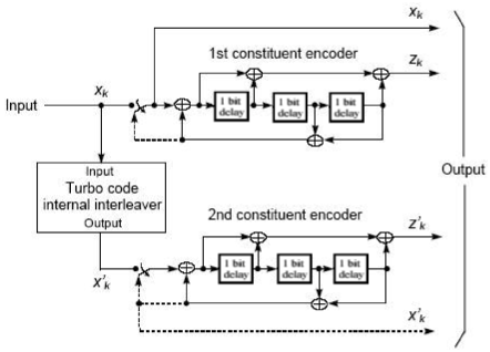
Wireless data systems of higher rates often use turbo coding, which are a combination of two convolutional coders reading each other (the name comes from the turbo-charged engine, which uses some of its output power to compress some air fed to the intake, and is somewhat reminiscent of the turbo coding diagram of figure 2.4).
Convolutional coding and turbo coding are example of continuous coding schemes, where a bit stream is encoded into another bitstream, usually of greater speed (with a multiplier of 2, 3, 4 or more). The added number of bits can be seen as spreading the spectrum, and the information, which requires more data to transmit, but inherently contains useful redundancy properties (a form of time diversity). The decoding of such schemes was historically difficult and has become possible only with recent processing power (see for instance Viterbi algorithms [115]).
The combination of modulation and coding provides great flexibility between redundancy and throughput. Higher modulation increases spectral efficiency in good propagation condition; when conditions worsen, lower modulation helps, but increased redundancy is sometimes an efficient alternative. Combined, the two schemes can reach impressive efficiencies, close to Shannon’s limit (§2.2).
We first briefly review current mobile digital technologies, how they were initially introduced, and how and they evolved. 3
| RF channel | 30 kHz |
| Reuse pattern | typically 7 |
| Duplex | FDD |
| Multiple access | FDMA |
| Multiplex | 1 traffic channel per RF channel |
| Voice | FM modulation |
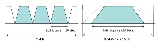
| RF channel | 30 kHz, 200 kHz in GSM, 1.25 MHz for CDMA |
| Reuse pattern | 7 (less with frequency hopping), 1 for CDMA |
| Duplex | mostly FDD (emergence of TDD) |
| Multiple access | FDMA, TDMA (8 full-rate time slots for GSM), or CDMA |
| Voice | Digital encoded: GSM full rate 13.4 kbps, CDMA 13 kbps QCELP or 8 kbps EVRC |
| RF channel | 1.25, 5, 10, 15 MHz |
| Reuse pattern | 1 (CDMA) |
| Duplex | mostly FDD, some TDD |
| Multiple access | CDMA |
| Voice | Digital encoded: bit rates 8 kbps and below |
| Data | Up to several Mbps (3.1 Mbps for EV-DO, 15 Mbps for HSDPA) |
| RF channel | generally wider: 10, 20 MHz, more |
| Reuse pattern | 1 (OFDMA) |
| Duplex | FDD or TDD depending on spectrum |
| Multiple access | OFDMA |
| Voice | VoIP |
| Data | IP based, flat architecture, convergence |
The introduction of digital wireless systems means that the acoustic voice wavefront is not simply converted to an electrical signal directly transmitted over RF channel. Voice is now digitized, encoded, and the resulting bit stream is transmitted and of course decoded on the receiving side. Although this process requires additional digital signal processing (DSP), it opens the door to many optimization algorithms and is much more efficient than usual analog voice transmission.
Digital voice coding (vocoding) is very important yet very subjective. Voice coding theory is a domain of study of its own; introductory overviews are presented for instance in [1] ch. 8 or [2] ch. 15.
Analog vocoders have emerged at Bell Laboratories in the late 1920’s, and have become more elaborate and efficient in dealing with harmonics important to a good understanding of voice (500 Hz to 3400 Hz) while minimizing bandwidth. The digital area brought significant changes. Initial digital systems sampled that range, which at the Nyquist rate leads to a 64 kilobits per second (kbps, kbit/s, or kb/s) bandwidth. This is referred to as pulse-code modulation (PCM). More elaborate algorithms however can achieve reasonably good voice transmission by transmitting a codebook (set of parameters for a given voice coding algorithm) with as little as 2.4 kbps rate: a 26-fold improvement. Usually these algorithms provide acceptable voice quality, but may provide poor performance in specific situations such as in a noisy environment, with background music, or when combined with different voice coding systems (such as PCM or voice mail systems). Several vocoder systems exist and have been chosen in 2G and 3G standards:
Comparing the quality differences between vocoder is usually done by testing a number of standard phrases, and assessing the quality of the transmitted result under various conditions. That assessment is subjective and is usually given a grade called Mean Opinion Score (MOS) between 0 (completely unintelligible) and 4 (perfect quality). Initial tests relied on actual opinion surveys, but test devices now offer algorithms providing a MOS and are regularly used by wireless network operators to benchmark network quality.
Second generation cellular systems certainly achieved major capacity improvements and contributed to the fast adoption of wireless handsets throughout the world. And the growth continues.
Third generation systems focused on increasing capacity yet again, and on introducing high-speed mobile data. Given recent heavy investments in different 2G networks, adoption of a common 3G standard had tremendous cost and competitive implications.
In 2002, CDMA Americas Congress (San Diego, December 2002) estimated that cdmaOne operators benefited from a smooth transition and a well-known standard, thus giving them a one or two year advance over GSM efforts towards UMTS. Indeed cdma2000 (3G 1X) systems have been available since 2002, IS-856 (3G-1X EV-DO) since 2004. GPRS and UMTS caught up around 2006. High-speed data services (HSPA) still lagged in coverage behind EV-DO in 2008.
According to most definitions (from the ITU in particular), 4G systems focused on increasing air interface efficiency to reach throughput rates around 100Mbps for mobility and 1Gbps for fixed wireless access. Additional requirements (mostly on the network infrastructure) such as low latency, flat IP architecture, small cells, and heterogeneous networks were specified as well.
Oddly enough two different camps emerged again: LTE and WiMAX, each backed up by different suppliers, and different operators, both using very similar technologies (based on OFDMA), yet unable to harmonize to a unique standard.
WiMAX continues to see some success in fixed wireless applications in developing areas. But practically the vast majority of the mobile industry is following LTE (since 2010), making it the de facto 4G standard.
5G standards are still in the works; an FCC order on 5G spectrum [14] notes no current intent to define what qualifies as 5G, but refers to standard bodies like 3GPP and the ITU. (See 3gpp.org 5G news).
Techniques largely revolve around LTE advances and focus on higher throughput, lower latency; they include: flexibility around many spectrum bands (including unlicensed, and millimeter-waves), higher order (even massive) MIMO, considerations for many more devices (Internet of things), direct device to device communications (D2D), and many more features described in releases 14 and beyond of LTE (see §8.3).
Recent technology advances aim at increasing capacity further. Technology improvements are sometimes the result of a major standard modification, but sometimes simple schemes that can be added to existing standards and allow for additional improvements with minimal infrastructure changes.
Voice coding algorithms and DSP capabilities have improved, and current voice codecs operate on less power, and with greater processing efficiencies. (Refer to [2] ch. 15, or [1] ch. 8 for speech coding details). GSM for instance is improving voice digitization and quantizing from RPE-LPT to a series of Adaptive Multi-Rate (AMR) standards. IS-95 systems have a parallel evolution, with EVRC (at 8 kbps), and half-rate EVRC.
Another standard for selectable mode vocoder (SMV) was in the work but never saw any success in the industry; it based requirements on: operation in presence of frame erasures, noise suppression recommended for background noises, reasonable performance with music for on-hold situations, equivalent performances with different languages, multiple quality modes and multiple bit rates, seamless transition from mode to mode. SMV was design to offer four modes of operations: from mode 0 designed to improve voice quality over EVRC with the same capacity to mode 3 for operators willing to sacrifice some voice quality robustness in order to realize a significant capacity gain. The resulting capacity vs. quality tradeoffs seem useful and attractive to service providers, yet this standard never took off, which may illustrate that some standard evolutions (even when based on sound requirements and good improvements) may miss their window of opportunity.
Voice over LTE (VoLTE), usually relies on wideband AMR with 9 different codec modes with data rates from 6.6 to 23.85 kbps.
For systems primarily designed for voice, latency was a main concern, and modulations were chosen to be reliable and operating well at fairly low SNR (like QPSK). For data systems it is advantageous to take advantage of higher modulation schemes such as 16QAM and 64QAM when the radio link allows it. Higher modulations are more spectral efficient but prone to more bit error rates and may cause more retransmissions, latency, or jitter.
Interferences may be cancelled or mitigated by changing antenna patterns as required. Such systems are sometimes referred to as smart antennas; they can steer a main lobe toward a user, or create a null in the direction of an interferer. Some systems are passive others include active amplification devices. The main types of smart antenna systems may be described as follows:
Smart antenna systems are efficient in dense areas but often costly [9]. They are now replaced by MIMO systems covered in chapter 9.
Technology advances and standard improvements target an increase in capacity, coverage, data rate, or some other system performance aspect. In many cases however some simple optimization techniques can be used to increase performance:
These techniques are very important tools used by operators to optimize capacity and coverage. In some cases optimization may be seasonal due to foliage or different usage patterns. In all cases RF network demand constant tweaking to provide optimal performance. More recently self optimizing networks (SON) have the ability to continually and automatically optimize these parameters.
Fixed wireless access is sometimes referred to as wireless local loop (WLL), and is an alternative to provide Plain Old Telephone Services (POTS) and high-speed data services in remote areas where wired solutions are impractical for various reasons. In most cases, trenching long distances to place communication conduits (for fiber or copper) is very costly, such as in mountainous areas. Cellular service is often scarce too in remote areas.
Radio solutions for wireless local loops were rolled-out extensively since the 1970’s. Early systems used analog radios to offer voice service over fairly long distances. Newer WLL systems need to be cost-effective, reliable, and compliant with local exchange carrier technical, legal, and regulatory standards. But the demand for WLL services are generally low, and suppliers consequently treat the opportunity as a fairly low priority.
Initially WLL focused on providing extensions of the public switched telephone network (PSTN) and its Class 5 features (such as call waiting, caller ID, 3-way calling, and others). Connectivity to Class 5 telephony switches is specified in Telcordia standards such as GR-303 or GR-008; and WLL systems evolved to use these standard interfaces to the PSTN.
Radio frequencies were allocated for wireless local loop applications, and are referred to as Land Mobile Radio (LMR). LMR radio links for telephony use frequencies in the UHF/VHF band (138-512 MHz), which provide great propagation characteristics even in difficult terrain and heavy tree density. These frequencies however are becoming very rare. In fact, they are in such demand that the FCC recently mandated radio systems to increase their spectral efficiencies, and use only a narrow band of spectrum. (See FCC order FCC-04-292, December 23, 2004.)
Other radio solutions work in the 2.4 GHz and 5 GHz unlicensed bands, building on economies of scale of 802.11 radios, with interference concerns - especially when providing emergency service (911 life line).
Fixed radio links usually behave differently from mobile radio links, they are typically less variable in time (therefore easier to predict and equalize), and their fading statistics are generally easier to deal with. Consequently fixed propagation is usually advantageous for a wireless system and has a significant impact on reach and capacity.
For all the above reasons, fixed wireless links often provide increased reach and capacity than equivalent mobile links.
The problem remains however to interface these systems with the telephony network. A VoIP gateway can be used to interface with the telephony switching fabric. Telcordia standards GR-008 or GR-303 for instance describe how to connect to a switch (over T1 lines), and access its classic telephony features (such as call waiting, caller ID, 3-way calling, etc.)
Several protocols are available to establish a reliable IP session that can provide voice transport, including session initiation protocol (SIP), or and Media Gateway Control Protocol (MGCP); ITU recommendation H.323 also provides interoperability standards for multimedia communications over IP including voice features. Modern standards generally rely on IP Multimedia Subsystem (IMS) to provide voice services.
Copyright ©2019 Thomas Schwengler. A significantly updated and completed 2019 Edition is available.